Again and again the question arises: how to control the motor on my machine with my Arduino. There are more solutions out there that one can imagine, special controller boards , shields, strange bus configurations, serial and parallel connections,… see here for many possibilities.
But what we need is a simple way that is easy to try for at least the first solution. Other [overly] complex solutions can come later.
We use the Arduino because it is simple, ubiquitous, powerful and cheap enough that if you blow one up, you will not hate yourself. In this post we assume that you can use your Arduino.
First thing: an Arduino can switch things on and off. One of the first experiments that you should make is the switching on and off of an LED using the Arduino. This is in File->Examples->Digital->Blink.
The next experiment is File–>Examples->Communication->Dimmer where the host computer controls the intensity of an LED. The Arduino program below does pretty much the same thing but with a more usual control – you can dim an LED directly from the Serial Monitor in the Arduino development environment. We will end up using this to control the speed of a motor.
This example is trying to do what we want to do, but it is slightly wrong. So let’s see how to do it right. We are doing two things: controlling the speed of a motor, which is equivalent to the brightness of the LED in the Dimmer example. And controlling the direction of the motor with a relay, which is the same as blinking an LED in the Blink example.
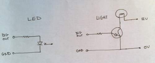
An LED requires around 20 milliamps (that is 20 thousandths of an amp) to glow. A decent motor requires anywhere between one half and 5 amps to move. The Arduino cannot supply this amount of power. So we have to use a switch in the form of a transistor to make this work. You can imagine a transistor as a LED that controls a switch. When the LED is on, the switch will close. So we could control a more powerful light, say a 12V halogen lamp needing one amp, with a transistor:
This is of course not really correct, engineers can tell you what is really happening, but for us it will do.
Note that, just like with a LED, we put a resistor in line (we say in series) with the transistor to control the current. Note also that we are switching a 12V lamp with the transistor, so we are not restricted to our 5V power supply. We can dim the lamp just like we dimmed the LED in the example. Try it.
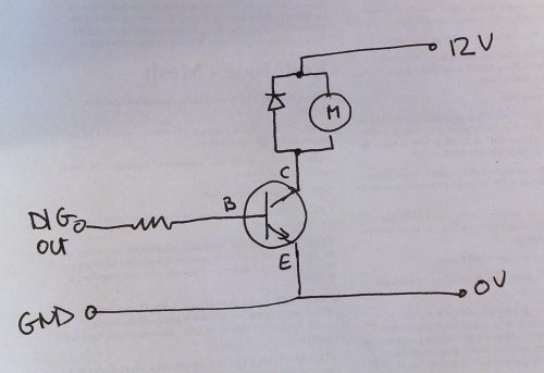
In principle all we need to now do is replace our lamp with a motor and we can control a motor just the same. There is one extra practical detail. When we switch a motor, or a relay, or a solenoid or pneumatic valve or any electromagnetic device off, a small current flows from it. This can destroy our transistor. So we use a diode to protect it. The diagram looks like the following:
A diode only allows current to flow in one direction, the direction of the arrow. So this diode in parallel with the motor does nothing as long as the motor is running normally, because the current flows down the diagram. When the motor is turned off, the current then flows through the diode rather then through the transistor and we do not blow anything up.
So how to build this? Go to some electronics store and ask for a (NPN) power transistor, a “Darlington.” It is also called the same word in German. There are loads of them. It will have a name on it, mine has BD 675 9 405. Go to http://www.alldatasheet.com/ and put in this number. It turns out that the real number we need is BD 675 because the last 4 digits mean something else. Lots of transistors have names like that: 2n222 or BD 679. So you end up here: http://www.alldatasheet.com/view.jsp?Searchword=BD675 and there are some PDFs to download. Get one of these.
What do we want to know? Most importantly, which leads are the Emitter, Collector and Base. This is sometimes on the first page, sometimes on the last page. Classically, power transistors have ECB as the ordering of the leads. But check. And re-check later before you turn it on.
What else do we find here? (Semi-technical paragraph – ignore if you want!) Most important are the maximal current allowed, called the “collector current,” I with a subscript C. For this transistor it is 4 Amps, which is fine for many applications. The next important factor is the “Collector Emitter breakdown voltage” which tells you what voltage you can switch. For the BD675 it is 45 V, for similar transistors on the same data sheet it gets up to 100V. This is the highest voltage you can safely switch with this transistor. One last magic number is the “DC current gain” called h with a subscript FE which for a Darlington transistor is usually somewhere between 500 and 1000. For the BD675 it is 750. This tells us how much amplification the transistor will make. So if we let 10 milliampere (10 mA) flow through the base, then 7500 mA = 7.5 amps will flow through the collector. Since this is more than we are “allowed” to, then only 4 amps will flow and our motor should not even need this much, so we will be fine. If we use a 1k-ohm resistor we will have around 5 mA current giving 3.75 amps of collector current: this should be enough in almost all cases, otherwise we can use a 470 ohm resistor.
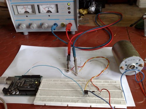
What else do we need? A 1 kilo-ohm resistor and a diode – we tend to use IN4001 diodes because they are big and hard to lose, easy to solder. The board then looks like this:
Blue wire from Arduino is Ground (GND), white wire is signal (pin 9). The power for the motor is yellow (GND) and red (12V). The motor is connected with read and blue wires. The connections can be seen here:
The transistor is mounted with the three leads being Emitter, Collector, Base in that order. The ground of the arduino and the power supply are connected to it. The collector has the wire to the motor and the diode attached. the band on the diode is pointed to the positive power supply lead which is also the other motor wire. The base is connected to the resistor (1k = brown black red) which is connected to the signal line from the Arduino board.
That’s it!
To control it the following program could be used. Put it in the Arduino window, save it, upload it, then use the Serial Monitor to control motor speed. You now have a basic motor control. Now make it do something interesting….. (in the next post I will add the relay to make the motor run in both directions).
/*

Speed / dimmer serial control.
received serial data from the host computer, controls the speed of a motor or the intensity of an LED based upon that serial data. The circuit: * LED or transistor/motor connected from digital pin 9. Use the Serial Monitor in Arduino to control the LED or motor. Based upon several Arduino tutorials */ int ledPin = 9; // LED connected to digital pin 13 /* state variables */ int value; int newvalue; // The setup() method runs once, when the sketch starts void setup() { // initialize the serial communication: Serial.begin(9600); // initialize the digital pin as an output: pinMode(ledPin, OUTPUT); // announce that we are running Serial.print("Starting\n"); // ask for input Serial.print("Enter a speed between 0 and 255\n"); } // the loop() method runs over and over again, // as long as the Arduino has power void loop() { int inbyte; // if new serial data is here while(Serial.available()){ if (newvalue < 0){ newvalue = 0; } inbyte = Serial.read(); if (inbyte-'0' < 10){ newvalue = 10*newvalue + inbyte -'0'; } delay(1); // seems to be necessary to allow the next byte to arrive } // if we have a new value if (newvalue != -1){ value = newvalue; newvalue = -1; // let the serial reader know we have taken this value // limit the values to the allowed range value = max (value,0); value = min(value,255); // tell the user what we are doing Serial.print("Received new speed: "); Serial.print(value); Serial.print("\n"); analogWrite(ledPin, value); // set the LED/motor PWM brightness/speed } }


